
Sourced and installed the parts from an RD350LC PMA into my blue rat some years ago . Used. Old. And still good. Very happy with it.
A year or so ago I picked up a nice low mileage 77 D. Ridden a few miles every year. Complete paper record. Had some charging issues.
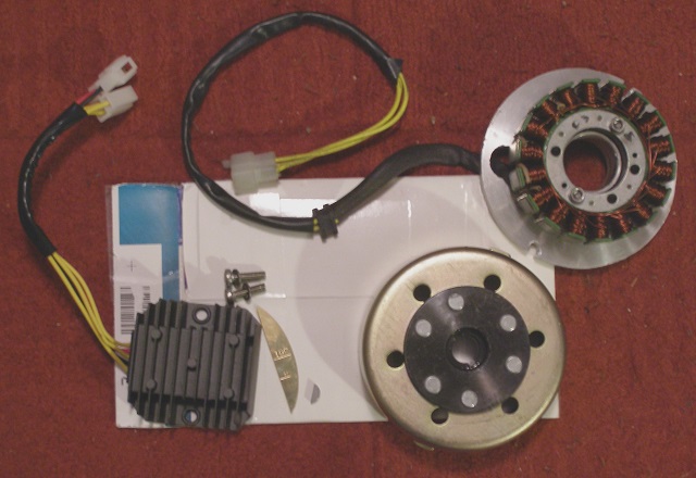
About this time Ants from the British XS650 forum began providing new PMA units for a good price. 200W. Complete with rec/reg, a rotor cone key that fit the original XS650 crankshaft and timing marks. (if trying the link dont be put off if you get a blank page – simply reset and it will appear – dont know why it does this but it happens to me all the time)
Was pretty busy for a while and it sat. Eventually got a chance to blow the dust off and begin.

Checking that the stator screws were loctited in – Yes.

Sometimes this locating pin just wont come out. Easier to quickly modify the backing plate

The pin sits at 6 o’clock so a simple line perpendicular to the horizontal gives the position

Backing plate didn’t sit properly over the crankshaft seal boss so got busy with a file. Would have been quicker to head off to the workshop and chuck it in the lathe. Naya.

Took a little while.

Sits perfect now.
Cut-out and reshaping will be now be done during production.

Phase wires held in place with a clip. Used another on the plate screw to the right just to keep clear from the chain and secured cable with a frame tie just below the rear engine mount.
Also removed the blue neutral indicator wire from the old loom, resheathed it in 4mm isolating sheath and reconnected to the original position. (Plug connector upper left in next pic)

This is the original regulator. Remove it.
The rectifier too. Sits under the battery box.

Remove the battery to release the rectifier.

Made a plate to mount the new 5 wire rec/reg in the original reg position so the fins didn’t block the airbox inlet. Would have welded tabs directly to the battery box but had run out of wire for the MIG. The 3 screws with nuts create an air space under the rec/reg for cooling and better air flow to the filter-box. Packed with rubber bushes they dont rub against the underside of the rec/reg.

Fits snug between the tool box and filter-box. Cables separated, resheathed and fitted with original connectors

Release the original connector blocks by inserting a small flat bladed screwdriver into the recess beside the pins. Simply push out.

Make sure the tangs are reset before reusing.

Added a 20 Amp flat bladed fuse holder in the positive battery feed. Just for security. This wire is too long and will be reworked.
The rec/reg, when mounted on the plate, interferes with the sidecover. Modified an old sidecover. Rattlecan-blacked it and it’s mate. Be a shame to mess up a good set of covers
Just got to put some kms on her now to road test before installing a 750 kit that’s been sitting on the shelf for a couple of years.
Had some charging issues in the beginning. Went through and checked the new wiring. Not quite sure what was wrong but the issues disappeared.
More than happy with this.
Update … almost killed my second rear tyre now – no problems – running sweet
Ant’s: This is a good product – once I installed it, 2.5 years ago, I have had no problems .. !!KOOL!!


You must be logged in to post a comment.