All internal combustion engines experience positive crankcase pressure. Primarily a function of blow-by gasses. Unburnt fuel/air, water vapour and combustion byproducts leaking past the rings. Into the crankcase space. As the engine wears the problem gets worse.
contaminates engine oil
contributes to sludge build-up
causes corrosion
promotes leaky seals
introduces windage (drag on the rotating crank caused by an oil cloud in the crankcase)
The parallel twin configuration – both pistons moving in unison – overlays alternate high/low pressure pulses onto this.
Solutions are either make it easier for the pressure to escape or create a vacuum (optimally 14-15 Hg/7 psi crankcase vacuum. More, sucks oil from the valve guides, rings and bearings). Vacuum can be created by pumping, one-way PCV valves, routing through the intake or exhaust and by dry sumps (the option used for Yamaha’s second foray into 4-strokes, the TT/XT/SR500). Systems can be open or closed.
Being 2-stroke people Yamaha knew a lot about crankcase pressure. Their first foray into 4-strokes, the XS650, gave them a few headaches however.
Originally they opted for easing pressure escape. A baffled, single orifice, open system vented to the atmosphere. The amount of oil/air was rather significant. This leaked like a true brit. Later, after experimenting with venting and baffle options they chose to run with a closed system routed through the air intake. Vacuum.
baffled, single orifice breather vented to the atmosphere … produced excessive oil … crankcase oil capacity spec 3.0 ltr
early single outlet breather
the next three generations of breather … twin orifice straight and angled and single orifice reduced box size, restricted outlet … baffle configurations were also changed throughout the series
The first 9685 machines apparently had a single outlet breather with single hose venting to the atmosphere. This was followed by a straight 2 spigot outlet, same baffles, also vented to the atmosphere. Spigots were changed (angled down) and baffles reworked. No effective change to excess oil leaking. They even tried plugging one spigot completely. Over-pressured the crankcase causing further leaks and blown seals.
Eventually vacuum was added by routing the 2 breather hoses directly to each air filter box. Closed system. Restriction plugs were added to each spigot. Again the baffles were reworked. The air intake becomes the vacuum source. Basically the engine is setup to consume it’s own blow-by gasses. Not brilliant. It coats the intake in oil residue, promote carbon build-up on piston crowns, combustion chamber, valves and lowers the effective fuel octane rating. The vapourized oil ignites at lowerenergy levels than 87 octane gas. The more that enters the cylinder, the higher the potential for detonation. A real issue for forced induction systems. It is, however, efficient, practical and good for the environment.
In the end the baffle box was resized. New baffle. Single reduced outlet. Single hose, split to feed each air box. Easier for carb removal.
steel wool baffle in original breather boxes … if this gums up pressure will have a problem escaping
baffles … left hand required 2 gaskets – this was modified to sit inside the box (later this was again modified, shortened, can just see it in the middle box, and the 2 plates shown were added – no steel wool) … the later box had a simpler single plate baffle as shown
baffle plate modified to sit nside the box … this was later shortened (as shown above) and 2 extra plates added
need to take care when using silicone type sealents – too much can block the return hole … oops!
venting to atmosphere, single hose, exiting above the chain
breather box with restricting plugs
Interestingly, early models specified 3000cc oil. Shell Thuet swore this was too much (and was ignored) only putting 2500cc in his motors. Eventually (’74/75) Yamaha’s engineers saw the light. Solved much of the oil leaking problem.
early cases – cast with oil spec, 3000cc – too much
eventually yamaha accepted Shell’s advice – 2500cc
specs modified again to allow for oil filters (when not removed during oil change)
tech bulletin M5-051 – 1975oil specs and dip stick modification
early open system vented to atmosphere
closed system schematic
early closed system airbox … blow-by gasses introduced after the filter, brfore the carbs – both sides
A common mod today is swapping stock air boxes for pods. Loses the vacuum effect (and may require rejetting). A one-way power brake valve can help here. It allows positive crankcase pressure to escape and prevents air returning when the pistons resume their stroke to TDC. A small vacuum is created helping seal rings and prevents oil leaks.
pod filters with breather pipe routed into the end … closed system
another attempt at replicating the original closed system
I have seen people use a short hose positioning the check valve over a pod filter. Any oil drips on the pod recontaminating the intake (and on only 1 side). Others pipe from the check valve back below the engine so any oil drips on the road. Hopefully off to one side and not on the tyre. OK if you enjoy cleaning your bike. If adding a filter ensure the hose ID and filterinlet OD match (12mm).
Using a catch-can resolves this and is relatively simple.
open system with catch-can
simple catch can
Fred Fleury’s soda catch-can
catch-can with filter … chromed
mine, made from an ikea pepper shaker
Comparison of differing methods of dealing with positive crankcase pressure.
OF
AF
CC
AP
DS
De-clutters the engine space
?
N
N
N
?
Simplifies crank case ventilation system
Y
N
N
N
Y
Helps remove more oil from the air
N
Y
N
Y
Y
Helps evacuate the crank case
N
Y
Y
Y
Y
Maintains or improves the stock flow capacity
N
Y
Y
Y
Y
Helps promote ring seal and prevent blow-by
N
Y
Y
Y
Y
Helps prevent oil smoke in exhaust
Y
N
Y
Y
Y
Helps prevent dip stick from popping out
N
Y
Y
Y
Y
Helps prevent oil leaks due to pressure
N
Y
Y
Y
Y
Helps keep intake track clean including carb body
Y
N
Y
Y
Y
Helps keep intake manifold/plenum clean
Y
N
Y
Y
Y
Maintains or reduces amount of pollutants
N
Y
Y
Y
Y
Maintains prevention of un-metered air from entering the intake
Yes, I like antique bikes. I race one, lol. Just realized that I have had an XS650 for over 30 yrs. Have my 1st one. Still. …I am the proud owner of a 78 ratbike (trophy winner) and a 650 drag bike.
… cowboy3669 at play
Where to start? After riding a 650 for about 10 years I had a good collection of complete 650s and assorted parts. So when I decided to start racing I figured ‘Might as well race what I got a good supply of parts for’. Cowboy was a nickname I was given over 20 years ago, 3669 is the # on my dragbike…..
.. my toy..
… man and toy … Ness fairing. Picked up at a swap meet years ago. Came without a wind screen. New one cost me more than the fairing did.
The biggest problem with running this engine is the lack of aftermarket parts. With the XS650 not being built since 1984 hi-performance parts are hard to find. Even some stock parts are getting hard to find.
… early version … The tank holds about 2 quarts and I cannot make two 1/4 mile passes on one tank full
There are not many people who drag-race the 650, so I had to figure a lot of things out for myself (lots of broken parts) … the turbo has been an ongoing project for about 6 years.
… turbo and clutch mods…nos bottle too
Started off with a basic bike, built a rigid back half. Ran that for couple of years. Then put nitrous on her. Ran that for couple more years. About 6 years ago put the turbo on.
The motor is stock bore & stroke (welded crank). Cam of unknown brand. A little more lift & duration. Home designed 3spd Transmission. Turbo off an Isuzu Probe GT diesel. Fogger nitrous injected. I’m using electric over air system. It shifts alright. Now the kill is sorted. 72 in wheelbase. Runs about 10,000 rpm at the finish line. The best has been 10.33 @ 133 mph .. average 10.80 to 11.20 @125mph. … weighs 680lbs with me on it. I weigh in at about 215 in street clothes…seasonally corrected.
Mighty impresive for an old XS
With the gearing (18/37) it is pretty close to the top end.
I have not put the bike on a dyno. Those calulators that input time or mph & weight approx it to be about 125 hp at rear wheel. But I think I’m producing well over 80 hp (10.33@133mph, 690 lbs.w/rider). The only cases I broke was when a gearbox problem pushed the shift drum out. Broke the boss that holds the retaining clip and 2 screws.
unfortunately more dramatic than it looks … bad turbo
I think there’s some more left in it. Has been 10.33. Right now I’m fighting wheel spin at launch. Could not get traction at 60°. The 5.5’’ tyre doesn’t hook like a 10’’.
Still gathering parts to try fuel injection. There are a few sources, atv’s, outboards and other bikes…Going to stay with gas. Been looking at automotive parts also. Have plenty to look at, seeing I work in a salvage yard. … Alky would be nice, but have to get this setup figured out first, lol.
Not sure of the cost. Ongoing project. What is the opportunity cost of fun?
… crank inspection port
Not the recommended way to inspect the crank. Happens when the rod wants to be somewhere else. A bad rod. There was oil in the engine right up to the time the rod made it’s great escape.
… valve contortionist
Two different actions. The valve spring retainer broke resulting in the bent valve.
Left a mark on the piston. But not broken. Broken valve guide. Replaced head, must not have been torqued correctly. Is now.
… carb… drawing thru a 38mm round slide … there is an aux pump that sends additional fuel to the carb under full throttle.
… oops … head gasket heaven
I ran a lot of nitrous at one time. About 70 hp shot. I had more problems keeping pistons in it than I did head gaskets. Now I have a fogger nitrous system. Found it important how much nitrous I was spraying. The nitrous is on for the whole pass. Amount is controlled by changing fogger nozzle jets. For the 133 mph pass I ran a 35 hp shot on each cyl. 14 lbs of boost. Since then I use less nitrous. Backed it down to 15 hp per cyl. Saves parts. And I’m still turning 10.80’s @ 125. Also changed the final drive ratio. Try to run 15-16 lbs boost
Remember seeing one in a Pommy ( English ) mag years ago … the bike he’s talking about is probably Orange Whip. Had NOS on it and to keep the topend on it had made up 2 side engine plates and a big plate over the head with bolts running down to side plates . Even then I thought it was overkill .
I’m running 3 speed. Stock shafts, gears and forks. Redesigned shift drum. I have the drum cut and welded to use 1st, 3rd and 5th gear. The 5 speed gave a best of 10.40 … The 3 speed so far has a best of 10.33 … 2 less shifts per pass.
It would be nice to have an auto but I have to ride back also. (He’s not talking about automatic activation, but engaging 2 gears at once, the lower gear popping out “automatically”. Like in prostock, A-street, comp, and mod bikes.)
I’m using electric over air system. Shifted alright. The kill worked overtime on the 2nd shift. .. I’m pretty sure the old switch was the problem, actually the brass part. The piston inside had gotten dried out before and had gotten stuck. Slow to return. Lube up the piston, problem usually stopped.
Me mate wanted to ditch the mechanical switch. Replace it. Wire directly in place of the old.
He had a few questions:
How do you have the air switch wired in? Is your air shift button supplying a + or – to the solenoid? .. …. the kill is wired in the + side of the coil where it’s been wired since I put a airshifter on the bike
Do you need the same kill time for both shifts? … Didn’t think I needed the same kill for the 2-3 shift.
Any idea what youre using for a kill time? ….. I was using the brass/micro switch so what ever the standard kill time is.
Stock coil and ignition? … Sent him a spare set.
Any idea how much current the coil draws? … ?????????
He was sure he could come up with something reliable. … And he did
There are four wires.
+ Power In – went to the old switch
Ground – needed to add this wire to the battery
+ Coil Out – went to the old switch
+ Trigger In – needed to run a new wire right from the air shift button or solenoid
Do not need a diode in parallel with the solenoid for this unit to work. If there is one, it’s fine.
New timer worked the same. Press button: supply + to the air solenoid and timer. The timer cuts power to the coil for some length of time. This dead time has nothing to do with how long you hold the button. It cuts power every time you push the button. Very simple, no frills. There’s a diagnostic LED. Turns on when power to the coil is cut. LED wont turn on if the wiring to the coil is bad. Just an easy check.
He said ‘Looks like shit. Cased in heat shrink tube. Filled, so vibration is no problem. Maybe 1″ X 1.5″ X 2″. Easy to find a place for. Or let dangle. Or not.’
He wasn’t sure what I needed for kill time so gave up to 150mS. I had the bike ready for the timer. Met one Saturday we both ran. Brought it with him. And the rain stayed away.
Afterwards he remarked ‘I bet you thought that it would never work!’ LOL. ‘I think you just need to play with it now. Put in a new line and get rid of the T fitting. Toss that old mechanical thing in a box somewhere for later.’
Good to be back in the 10’s….Sweet!!.
Time to fine tune. And remount.
I’m using a IHI off a Probe GT. Carb is a 38mm round slide mikuni. Internal wastegate. 15-16lb’s boost. The oil feed comes out of the right side cover by the outlet from pump. The outlet is connected to a small 12 volt pump that pumps the oil into a fitting that is in place of the neutral light switch.
Some things to think about:
Oil heat- Do you need to put a cooler on the turbo oil feed line ?
Stock oil pump- Can it keep up with the turbo and the rest of the engine? If the stock pump can feed oil coolers ok, can it run a turbo too ?
Oil return-Is it better to put the turbo up above the case oil level so you dont have to run a return pump-gravity return ? What about putting the turbo out front, as low as possible, as close to the center as it will fit ? Keeps a short header for spool purposes.
Blowthrough needs a fuel pump- Can the stock electrical system handle the draw with everything else on?
H20 injection ? – Better than an intercooler ? For shorter intake plumbing and less crap hanging off the bike. Would it mess with the carbs to have water going through there ?
Boost ? – With stock pistons, pump premium, and no intercooler maybe 10psi max? … Depend on the turbo I suppose.
This guy ( Kev from Oz) is doing some pretty far out stuff as well as the turbo but definitely has some awesome ideas like that AWIC. (air/water intercooler–very nice, but xstra weight)
Here are some pics of the pump I use to transfer the oil from the turbo back to the engine. The pump is a generic fuel pump from Autozone. I think it cost me 25 or 30 dollars.
… pump and plumbing
…
…
This where I tapped into the side cover for the feed to the turbo. … haven’t had any problem with the line. Only wrecked one turbo because of lack of oil pressure. The line was plugged.
… oil feed direct from pump…lots of flow
That line is tapped right at the pump outlet. There may not be much pressure but there is a lot of flow.
Not running coolant lines. The feed line for the oil comes off the right cover at the outlet from the filter. The return (drain) from the turbo goes to a small electric fuel pump, and is returned to the engine at a fitting in the cases above the trans – neutral switch. Most of the parts were already in my stash. Not sure on the A/R.
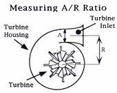
A/R, Aspect Ratio, is the rated volumetric efficiency of a turbos 2 sections
measuring Aspect Ratio
Picking A/R comes down to spool time vs. top end power band.
You need to decide where you want your power band and plan accordingly from the start.
Not only Power band should decide A/R, but cam selection, heads, intake compression ratio, rear gears ….. there’s a lot to this and no magical method or perfect right or wrong answer.
… no intercooler – dont want a bomb…this long tube is part of the intake
No intercooler. With the draw thru, an intercooler will let the fuel fall out of suspension (turns the intercooler into a bomb). The long tube on my system is just part of the intake tract. I think draw thru systems make just about the same amount of power. They’re just a little less compilcated …. Don’t know if it’s any better to have a long intake but I didn’t have room to put the turbo behind the engine like most draw-thru systems do. So out front it went. Seems to work alright for this set up.
Lag, the problem with using too large of a turbo. That’s why I use nitrous. No problem now.
Lag can be reduced in a number of ways. ( Not to be confused with Boost Threshhold)
by lowering the rotational inertia of the turbocharger; for example by using lighter, lower radius parts to allow the spool-up to happen more quickly. Ceramic turbines are of benefit in this regard.
by changing the aspect ratio of the turbine.
by increasing the upper-deck air pressure (compressor discharge) and improving the wastegate response; helpful – cost and reliability disadvantages.
by reducing bearing frictional losses; using foil bearings rather than conventional oil bearings reduces friction contributing faster rotational acceleration.
Variable-nozzle turbochargers greatly reduce lag.
by decreasing the volume of the upper-deck piping.
by using multiple turbos, sequentially or in parallel.
The gauge reads about 15-16lbs of boost. I estimate about 100+ hp.
Not sure about what size turbo would be best for the street. My turbo came off a 2200 cc engine. I use nitrous to help spool up. No idea how mine would work on street without the nitrous.
There so few of us putting turbo’s on XS’s. All we can do is fab the systems up and work from there.
If you’re gonna go the extreme of installing a turbo, you might as well address the lazy ports on the XS head. Assists the breathing and expelling of burnt gases.
The clutch is a weak spot, especially running nitrous. I had a Suzuki clutch for a couple of years, but the basket broke (big mess). Still needed periodic maintenance due to slippage .
… banshee centrifugal assist…makes a difference
This is the clutch in the dragbike. Now. A stock 650 clutch pack. And lockup. From a Banshee. The centrifugal assist was made for the banshee. Had to modify the holes to the spacing of the xs bolt centers, approx 0.030 out. I also had to make spacers for the springs and to get the lock-up head in the right position. And redo the side cover.
… 3669
… .and again … go yamaha.. the fuel tank part is actually the result of using a stock tank as a mold.I cut the tank at the seam, laid up fiberglass inside. then molded to the body I made .
Some other interesting dragxsters…
orange whip … burnt out, the proverbial phoenix – rose from the ashes to become Whiplash .. see the plates and external bolts – to hold the head on
kenny d … Back in the ‘day’, safety was not paramount (nice gloves & boots!) … not an XS but I liked the pic
sprint … limeyland
… supercharged
… from the late 70s. It was run on alcohol. Air shifter, total loss MSD ignition.
… re-phased crank and cam, transmission cut off the extra cases, frame stretched fifteen inches … Dyna ignition set up with a Suzuki advancer for the rear motor, both motors lit with dual output coils.
… 70′s Twin-Engine Yamaha Drag Bike. This twin-engine top fuel drag racer was built in the early 70′s , recently only used as a static display. These bikes were started on a set of rollers using a car as power. Pull in the clutch, get the rear tire spinning on the rollers, and fire the bike. These were high gear only affairs, and ran in the 170 mph range. One throttle operates all four carbs, and one clutch lever on the handle bar operates rear motor clutch and trans. The motors are connected using a Gates-Gilmer type belt… A new M+H Racemaster slick is mounted out back with a new smooth hard rubber race only tire on the front…nicely designed and constructed… It is scary to think about how much power is accessible via that little chrome clutch lever. The front suspension design is interesting on its own, and the long frame and engine placement means no wheelie-bar.
another twin
… from Dutch Trash Choppers
… Check out this wild XS650 drag bike project. The cylinderhead is turned around backwards. The front wheel is from a Puch Maxi moped.
For a run down on reverse heads check out Terry’s site. Scroll down.


You must be logged in to post a comment.